1.- Introduction
Proxmox is an open-source virtualization solution ideal for environments requiring high availability (HA), especially in setups with multiple servers and centralized storage, such as a Synology NAS. It provides the capability to manage server clusters and dynamically move virtual machines, maximizing resource availability.
This guide focuses on implementing a datacenter with Proxmox VE, using three servers and a Synology NAS to create a high-availability infrastructure, ensuring that virtualized services remain online in case of hardware failures or overloads.
Here we provide a brief introduction on why it is ideal:
- High Availability (HA): Proxmox offers a native high availability feature. This means that if one of the servers fails, the virtual machines running on it can automatically migrate to another server in the cluster without significant downtime. In a three-server setup, Proxmox would manage this migration efficiently.
- Cluster Management: Proxmox allows you to create server clusters to centralize resource management. With three servers, you can distribute the workload and enable virtual machines to move between them dynamically (live migration), maximizing availability and efficient resource use.
- Integration with Centralized Storage: With a Synology NAS, you can configure shared storage accessible from all servers in the Proxmox cluster. This is crucial for high availability, as virtual machines must be able to access their disks regardless of which server they are running on.
- Support for Multiple Virtualization Technologies: Proxmox allows the use of both virtual machines (KVM) and containers (LXC), giving you flexibility to choose which technology to use for each workload according to your needs.
- Ease of Use and Administration: Proxmox offers an intuitive web interface for managing the entire virtual environment, making it easier to administer the cluster, virtual machines, and containers.
- Redundancy and Fault Tolerance: The combination of Proxmox and centralized storage on the Synology NAS ensures that data is secure and accessible, even if one of the nodes fails, as the rest of the cluster can still access the NAS data
In summary, by using three servers with Proxmox and a Synology NAS, you get a scalable, high-availability solution that ensures virtualized services remain online even in the event of hardware failures or resource overloads.
2.- Prerequisites
To set up a High Availability structure with Proxmox, the following are required:
- 3 Servers with similar specifications
- 64 GB RAM (recommended)
- 256 GB SSD (recommended)
- Intel I9 12th generation, 20 cores (recommended)
- 2 Network Interfaces: one for management and the other for our cluster
Average price on Amazon: US$ 600.00 per server
- Synology NAS Server with enough capacity to store all the virtual machines to be created.
Other Linux-based NAS systems can also be used, requiring mini servers with high storage capacity.
Average price on Amazon: Synology DS224+ 2×4 TB: US$ 600.00
Total Initial Investment for our Datacenter: US$ 2,400.00
Our structure will include three machines and a shared iSCSI storage server.
Configuration Data:
Node 1:
Machine Name: pve01
IP: 190.168.10.100
Node 2:
Machine Name: pve02
IP: 192.168.10.110
Node 3:
Machine Name: pve03
IP: 192.168.10.120
NAS Server for iSCSI
IP: 192.168.10.7
Note:
- To expand our Datacenter, simply add a fourth or fifth Proxmox node.
- For external access to virtual machines, a public IP is required for each instance created.
- Although Proxmox includes a firewall, it is recommended to place a firewall in front of our Datacenter.
3.- Configurations
3.1.- Proxmox Installation
Proxmox VE (Virtual Environment) is an open-source virtualization platform based on Debian that enables the management of virtual machines and containers in a unified environment. It offers advanced tools such as high availability (HA), clustering, backups, and support for various types of storage, making it an ideal solution for efficient IT environment management.
Installation Steps
1. Create an Installation Media
First, create a bootable media using the Proxmox VE ISO:
a. Download the ISO from the official site:
https://www.proxmox.com/en/downloads
b. Use a tool like Balena Etcher to create a bootable USB with the Proxmox ISO, or burn the ISO onto a CD/DVD: https://etcher.balena.io/
2. Boot from the Installation Media
a. Insert the USB or CD/DVD into the server or device where you want to install Proxmox.
b. Configure the machine’s BIOS/UEFI to boot from the USB or CD/DVD.
c. Restart the machine and select the bootable installation media.
3. Install Proxmox VE
Once the machine boots from the installation media, follow these steps:
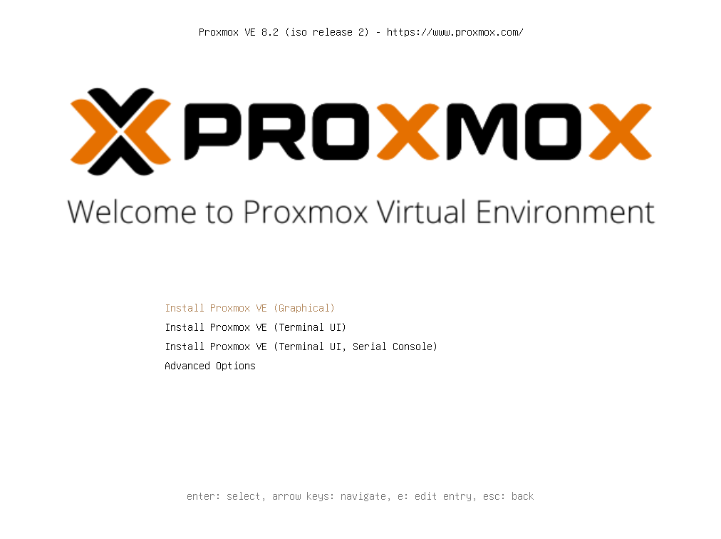
a. Welcome Screen: You will see the Proxmox welcome screen. Select Install Proxmox VE and press Enter.
a. Accept License Terms: Read and accept the EULA (End User License Agreement) to proceed with the installation.

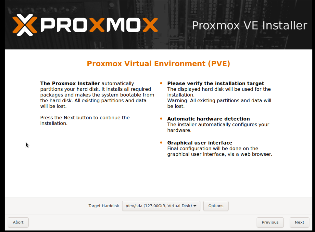
b. Select Installation Disk: Choose the disk where you want to install Proxmox. Make sure to select the correct disk, as this process will erase all data on it.
c. Set Region and Time Zone: Configure the time zone and keyboard language.

d. Set Password and Email: Set the password for the root (administrator) user and provide an email address for system alerts.

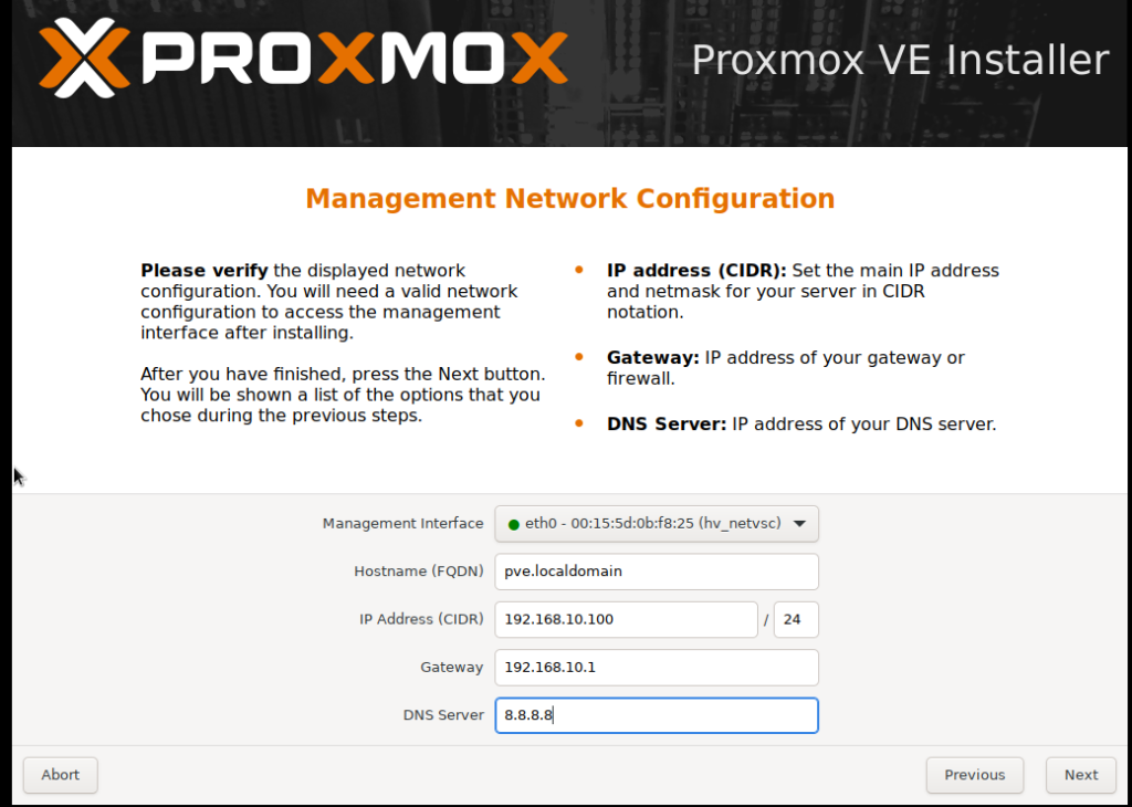
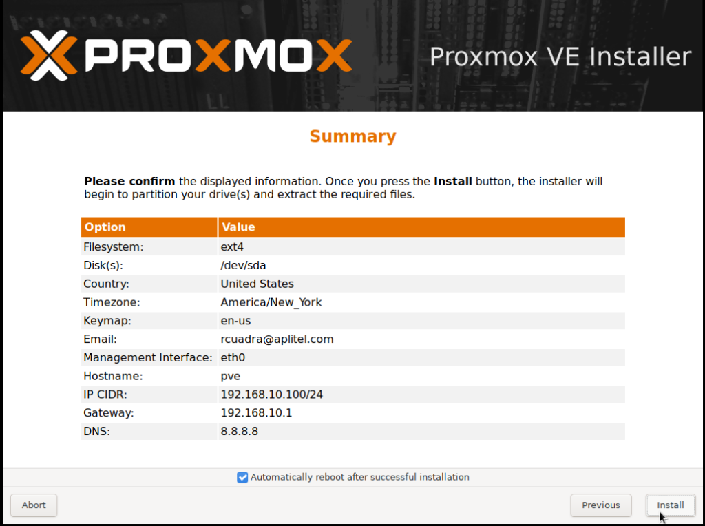
e. Configure Network: Assign a static IP address for the network interface. This address will be used to access the Proxmox web interface.
f. Finish Installation: Verify the configuration and press Install. The installation may take a few minutes. Once completed, remove the installation media (USB or CD/DVD) and restart the server.
4. Access the Web Interface
a. Once the server has restarted, open a web browser from a computer on the same network and access Proxmox using the IP address configured during installation:
https://[server IP address]:8006
Ejemple: https://192.168.10.100:8006
b. When accessing the URL, you may receive a security certificate warning. You can ignore it and proceed.
c. Log in with the root user and the password you set during installation.
5. Update Proxmox
Once inside the web interface, it is recommended to update the system:
a. Open a shell from the interface or connect via SSH.
b. Run the following commands to update the system:
					apt update
apt dist-upgrade
Once we have completed the installation on our three servers, we will proceed to create the cluster.
3.2.- Cluster Configuration
3.2.1.- Cluster Creation
On Node 1, go to Datacenter/Cluster and create the cluster by clicking Create Cluster.
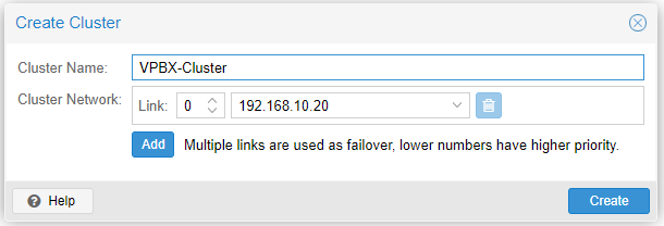
Cluster Name: a short name to identify our cluster.
3.2.2.- Node Assignment to the Cluster.
Now, in Datacenter/Cluster, click on ‘Join Information’ and copy the data we will use to add the other nodes.

Now go to Node 2 with the information copied from the previous step, and in Datacenter/Cluster, click Join Cluster.
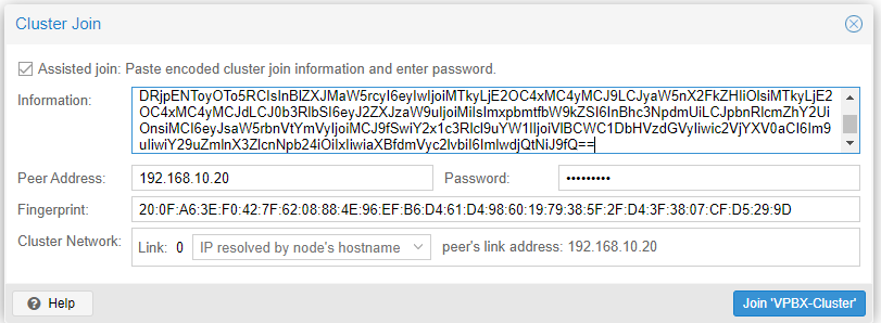
Enter the root password for Node 1 and click Join ‘VPBX-Cluster.’ Wait a couple of minutes, and your node will be assigned to the cluster.
Repeat the process with Node 3, and you’ll have a 3-node cluster, which is the minimum recommended for high availability.
3.3.- iSCSI Storage Configuration.
In this example, we will use a Synology NAS with a capacity of 2TB to configure iSCSI storage. This resource will allow the NAS space to be used as storage for other systems, such as Proxmox.
3.1.1.- Access Synology
1. Log in to the administration interface of your Synology NAS.
2. Navigate to SAN Manager from the system’s main menu.

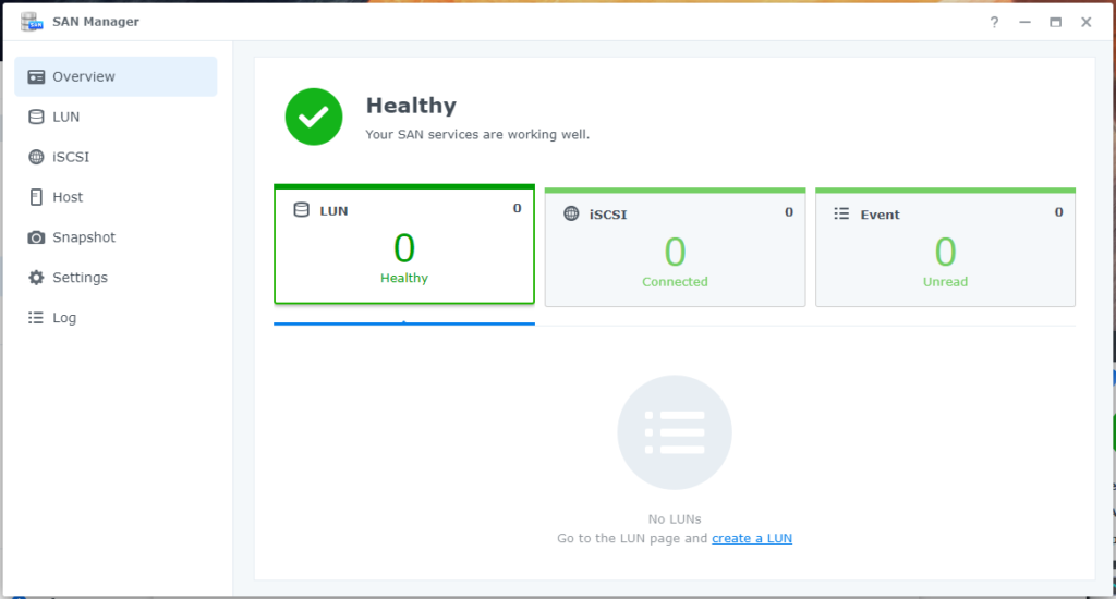
3.1.2.- iSCSI Resource Creation
1. Inside SAN Manager, select the iSCSI option from the side menu.

2. Click on Add to start the iSCSI shared resource creation process.
3. The setup wizard will open. On the first screen, select ‘Create a new iSCSI Target.
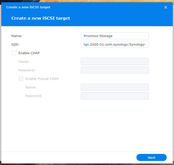
4. Assign a descriptive name to the iSCSI Target that clearly identifies its purpose or content. Then, click Next.
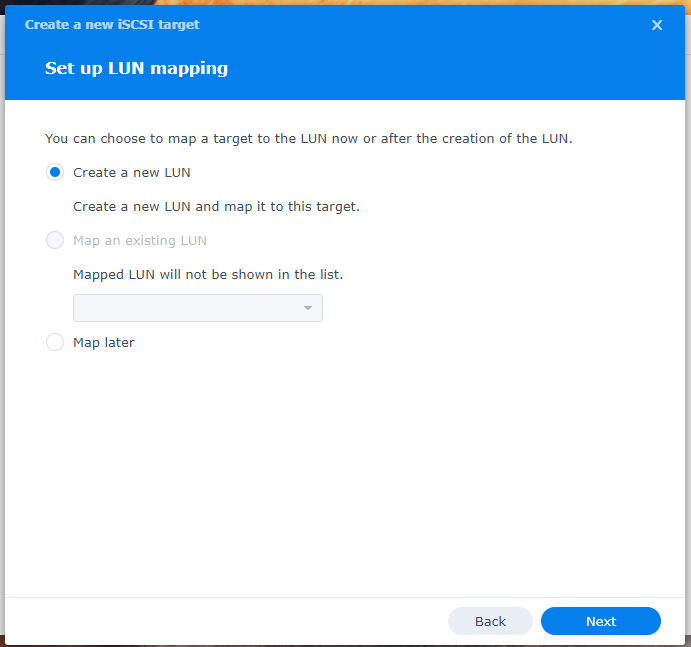
5. Next, select ‘Create a new LUN’ to create a logical unit where the data will be stored. Press Next.
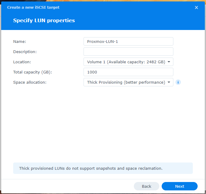
6. Assign a descriptive name to the LUN and specify the disk size you wish to allocate to this shared resource. Keep in mind the storage needs of your systems. Click Next to continue.
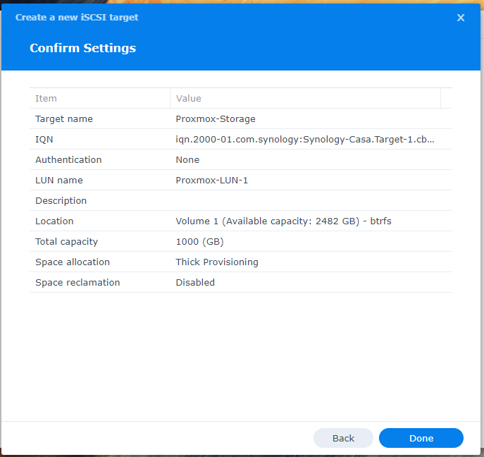
7. Review the configuration you’ve entered. If everything is correct, click Done to complete the creation of the iSCSI Target and the LUN.
3.1.3.- Advanced Settings
1. With the iSCSI Target created, select the newly configured resource and click Edit to make some additional adjustments.
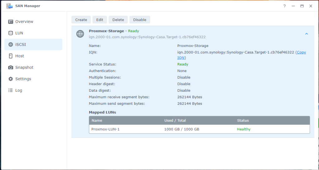
2. Go to the Advanced tab.
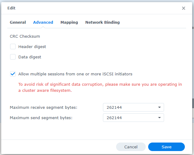
3. Enable the ‘Allow multiple sessions’ option. This allows multiple systems to connect simultaneously to the iSCSI shared resource, which is useful if the storage will be accessed by multiple servers or services.
4. Next, go to Network Binding.
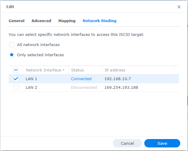
5. In this section, specify the network interface that will allow connections to the resource. In this case, select LAN 1 to restrict connections through that specific network interface.
3.1.4.- Configuration in Proxmox
1. Now that the iSCSI resource is available on the NAS, it’s time to configure it in Proxmox.
2. Access the Proxmox administration interface and select Datacenter from the left panel.
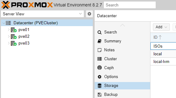
3. Click on Storage and then on Add.
4. From the dropdown menu, select iSCSI.
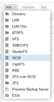
5. In the iSCSI configuration form:
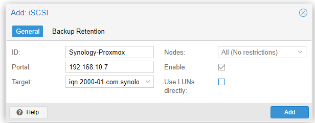
• ID: Enter a descriptive name for the iSCSI storage.
• Portal: Specify the IP address of the Synology NAS where the storage is configured.
• Target: Select the iSCSI Target you just created on Synology. Typically, this field can be left at its default if you only have one Target.
• Nodes: Leave this option set to be accessible by all nodes in the Proxmox cluster.
• Enable: Ensure this option is enabled.
• Use LUNs directly: This option should remain disabled unless you need direct access to the LUNs.
6. Once the iSCSI storage is created, it needs to be linked with LVM storage to allocate disk quotas to each Virtual Machine. Proceed with the following steps.
a. Go to Datacenter/Storage, select the iSCSI Storage created, and click Add.
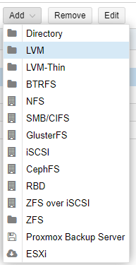
b. Now, in the form, enter a descriptive ID, select the Base Storage, which is the iSCSI, and then select the Base Volume. Assign a group name to the new volume. Proceed by clicking Add.
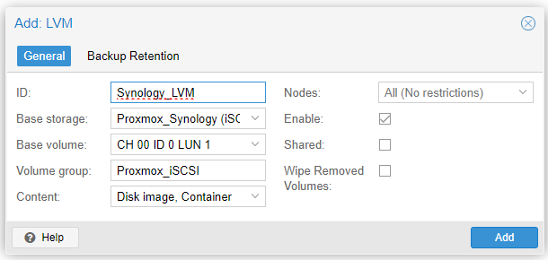
7. Finally, review the configuration and save the changes. The LVM iSCSI storage will now be available in Proxmox to be used as shared storage among the nodes.
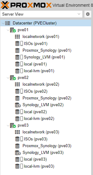
We can now see the shared storage resource Synology_LVM.
3.4.- Creation of Storage for ISO and Templates
Next, we will create a Directory to store the ISOs and Templates needed to create Virtual Machines (VMs) or Containers (CTs).
1.- On each of our nodes (1, 2, and 3), access the console and create a folder where all our ISOs and Templates will be stored.
					cd /home
mkdir ISOs
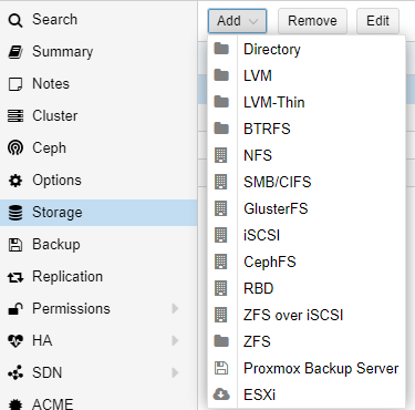
2.- Go to Datacenter, then Storage, Add, and select Directory.
And in the next form, fill in the information as shown below.
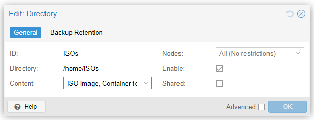
Once this resource is created, we can proceed to create a VitalPBX instance on our Node 1 (pve01).
3.5.- VitalPBX Virtual Machine (VM) Creation
First, upload the latest Debian 12 ISO to our previously created Directory (ISOs /home/ISOs). Go to ISOs/ISO Images/ and click ‘Upload’ to load the ISO.
https://cdimage.debian.org/debian-cd/current/amd64/iso-cd/debian-12.7.0-amd64-netinst.iso
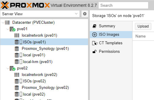
Select the ISO by clicking “Select File” and then press “Upload”
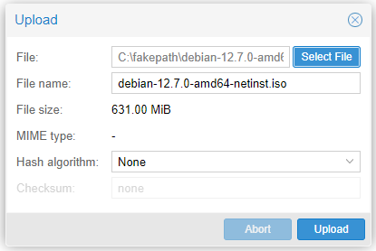
Once the upload is complete, proceed to create our Virtual Machine (VM).
Now we proceed to the creation of the Virtual Machine. Position yourself on Node 1 (pve01) and press the ‘Create VM’ button
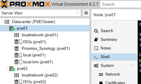
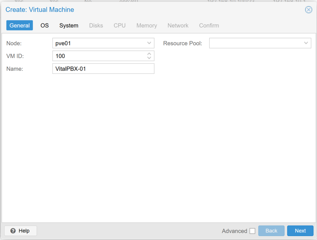
We select the Node: pve01, leave the VM ID: by default and write a descriptive name for our Virtual Machine. We press Next.
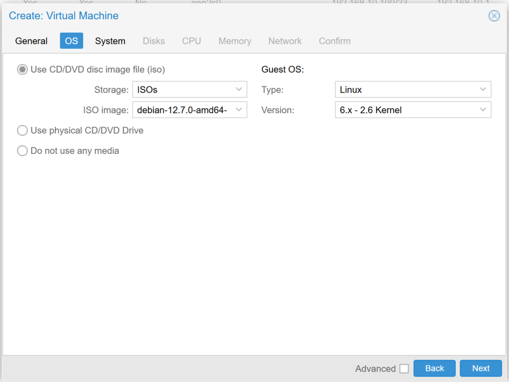
Now, we select the Storage where the Debian 12 ISO is, and select the previously loaded ISO. We verify and press Next.
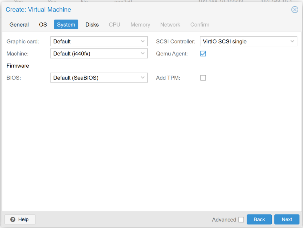
In the System options, we select “Qemu Agent” and leave the rest by default.
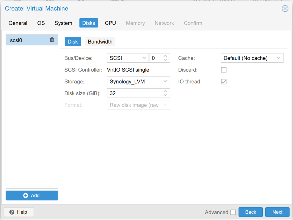
Now we select the created Storage (Synology LVM) as shown below. And we assign the hard disk quota that the Virtual Machine will have.
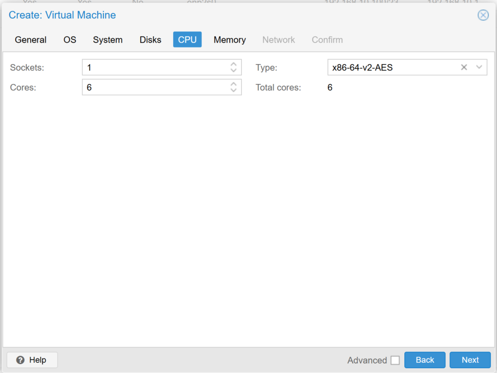
In the CPU section we select how many cores we want to dedicate to this Virtual Machine, we recommend at least 4 cores if it is a VitalPBX that will handle more than 100 extensions..
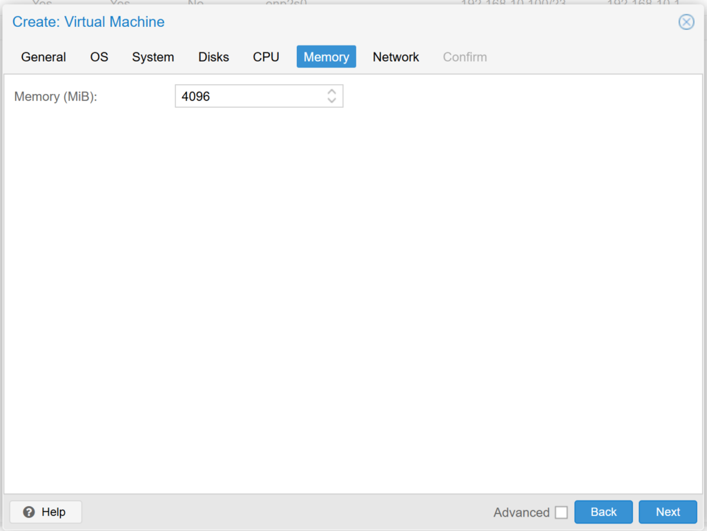
In the memory section we configure the amount of memory that our Virtual Machine will have assigned, we recommend at least 4GB for an implementation of more than 100 extensions.
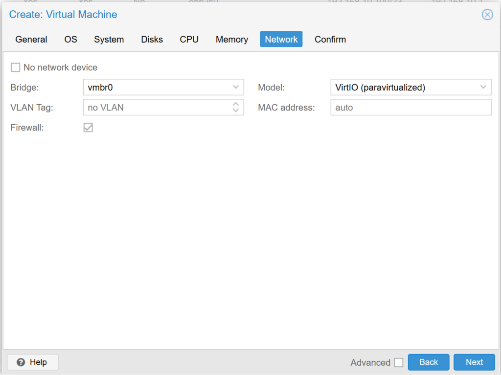
In the Network section we select the network through which you will have access to our Virtual Machine.
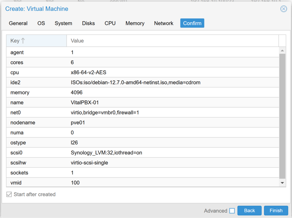
Finally, we confirm the configuration and we will proceed to create our Virtual Machine.
Once our Instance (VM) is created, we will see it listed in our left panel, we press it with the right mouse button and start it (Start). We enter >_ Console and install Debian 12.
After installing Debian 12 we will proceed to install VitalPBX.
					apt install sudo
apt update
apt upgrade -y
wget https://repo.vitalpbx.com/vitalpbx/v4.5/pbx_installer.sh
chmod +x pbx_installer.sh
./pbx_installer.sh
Once the creation of the VM is finished, remember to go to VM/Options and enable “Start at boot”, otherwise when restarting the server our VM will not start automatically.

Once our Virtual Machine has been created and VitalPBX installed, proceed to clone it to use it as a template when creating another Virtual Machine with VitalPBX already installed. You must leave the network configuration in DHCP to create it as a template..
To clone a VM in Proxmox and use it as a template to create new machines, follow these steps:
1. Shut down the VM
• Before converting the VM to a template, make sure it is shut down. You can do this by selecting the VM and clicking “Shutdown”.
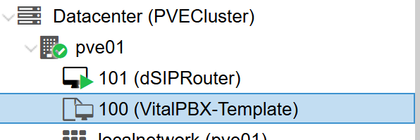
2. Convert VM to Template
• Once shut down, right click on the VM in the left side menu.
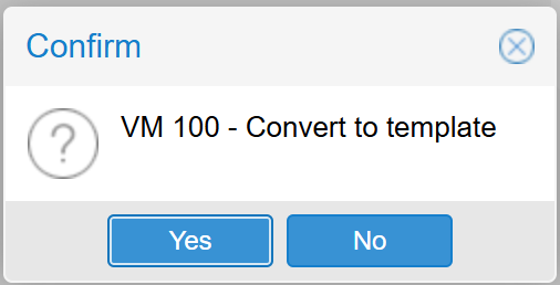
• Select “Convert to Template”. This will convert it to a template and you will not be able to start it until you convert it back to a VM.
3. Create New VMs from the Template.
• Once you have the template, you can clone the template to create new VMs:
a. Haz clic derecho en el template.
b. Selecciona “Clone”.
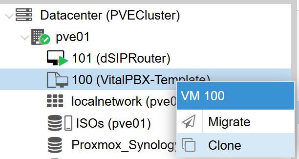
c. In the pop-up window, select the option “Full Clone” (this will create a complete, stand-alone copy of the template) or “Linked Clone” (creates a VM linked to the template, which uses less space, but depends on the template).
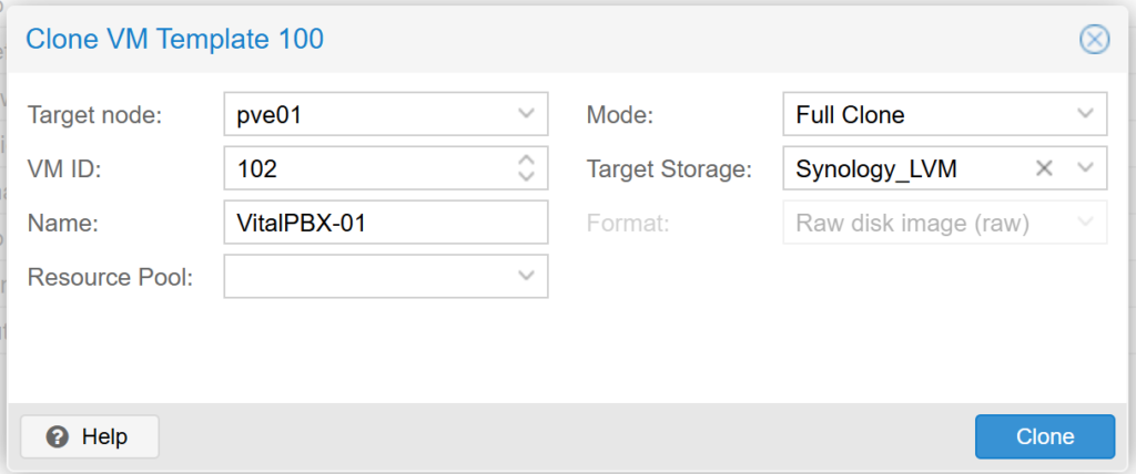
d. Assign an ID and name to the new VM.
e. Specifies the node and storage where the cloned VM will be stored.
f. Click “Clone” to create the new VM.
4. Additional Configuration
• Once cloned, you can adjust the specific settings of the cloned VM, such as the amount of CPU, RAM, and other resources.
This process makes it easy to create multiple VMs with identical base configuration.
3.6.- Creating a VitalPBX Container (CT) (Not recommended)
First we are going to load the Template of the latest version of Debian 12 into our previously created Directory (ISOs /home/ISOs), for which we go to ISOs/CT Templates/ and press “Templates” to load the Template.
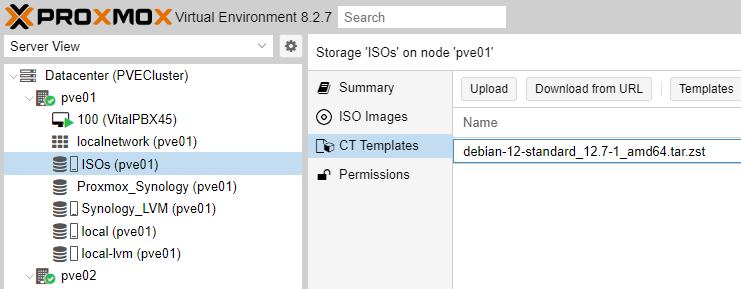
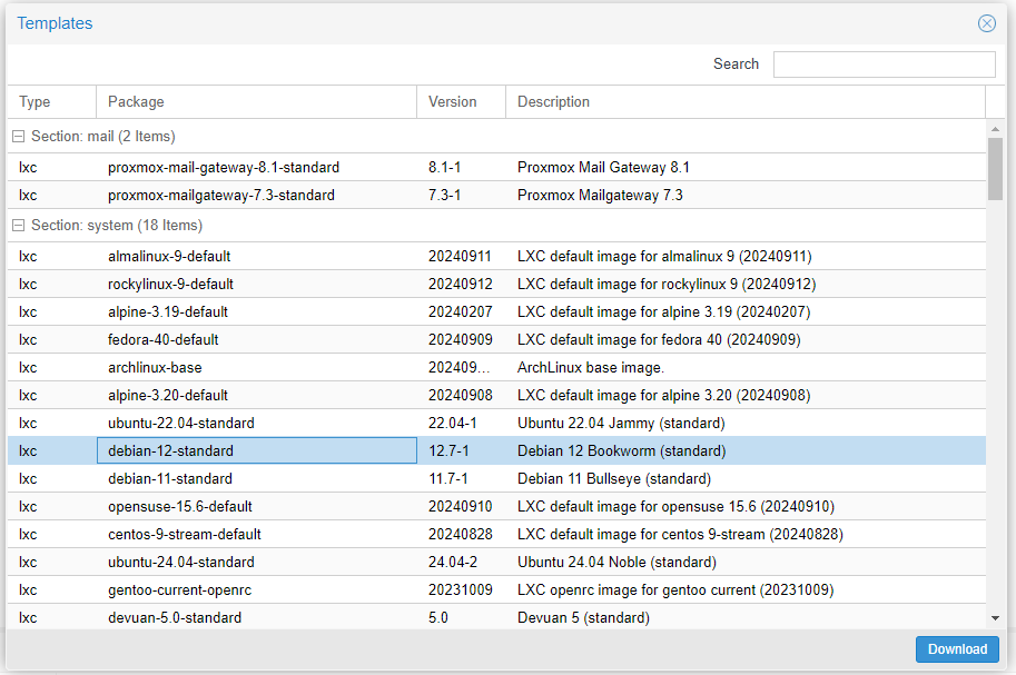
We select the Template and press “Download”
Now we proceed to the creation of our Container.
We position ourselves in Node 1 (pve01) and press the “Create CT” button.

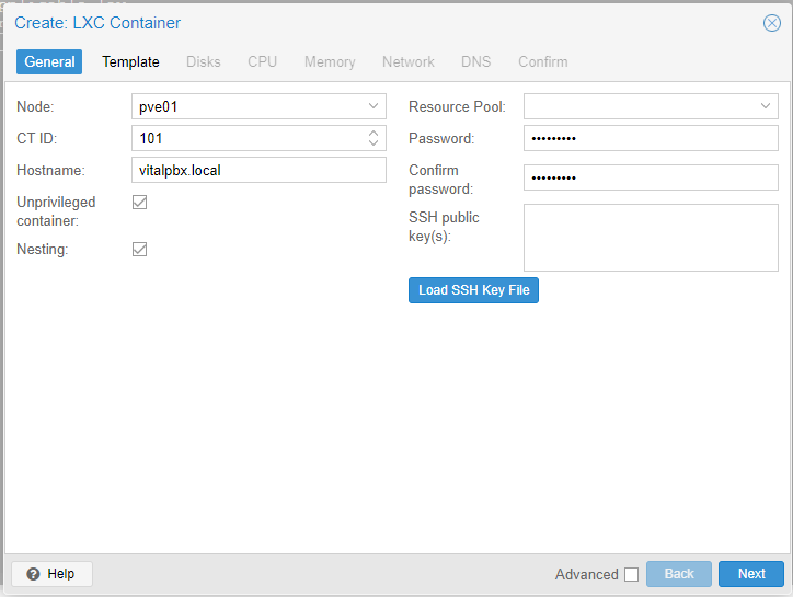
We select the Node: pve01, leave the VM ID: by default and write a hostname and the password of the root user that we are going to use. We press Next.
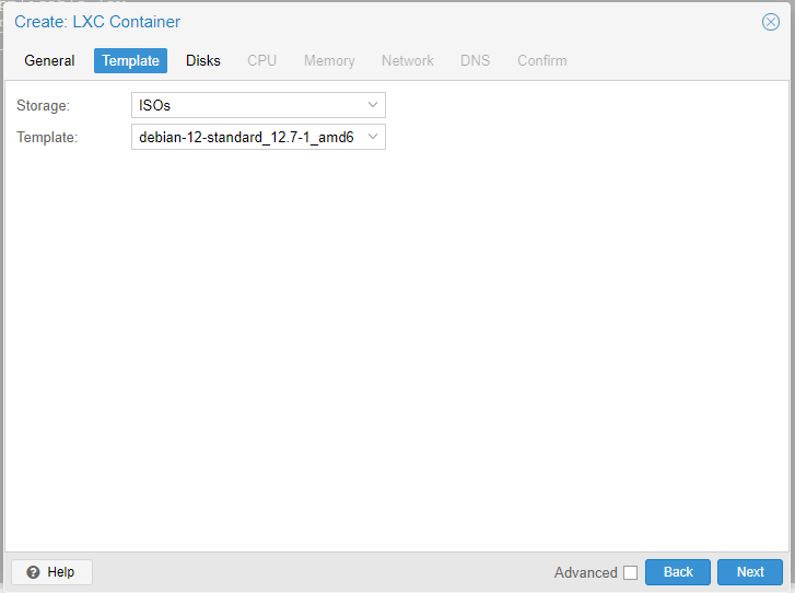
Now, we select the Storage where the Debian 12 Template is, and select the Template uploaded previously. We verify and press Next.
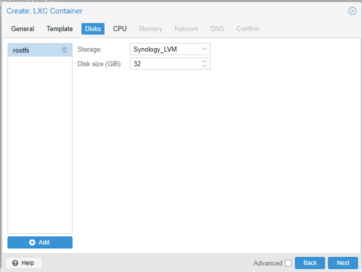
Now we select the created Storage (Synology_LVM) as shown below. And we assign the hard disk quota that our Container will have.
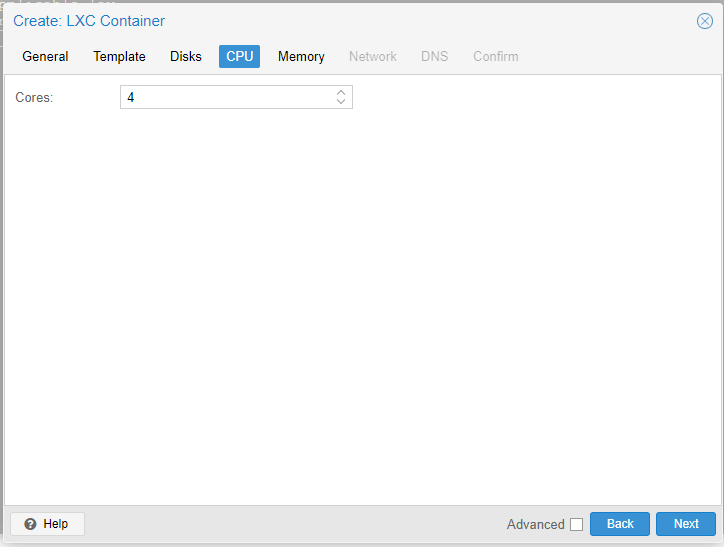
In the CPU section we select how many cores we want to dedicate to our Container, we recommend at least 4 cores if it is a VitalPBX that will handle more than 100 extensions..
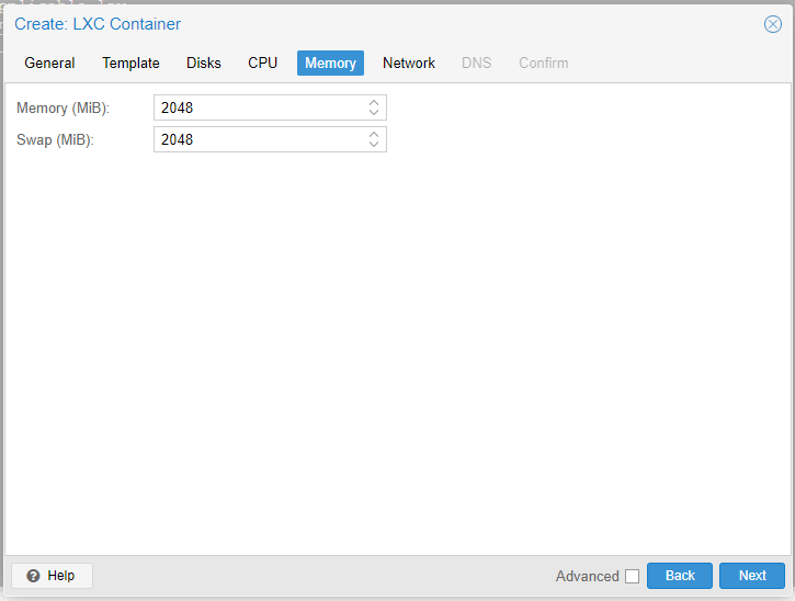
In the memory section we configure the amount of physical and swap memory that our Container will have assigned, we recommend at least 4GB for an implementation of more than 100 extensions.
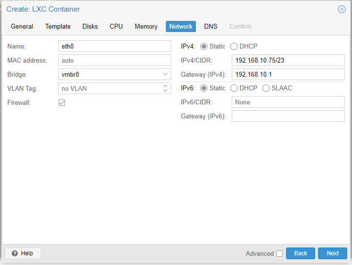
In the Network section we select the network through which our Container will have access as well as the IP that we are going to assign to it.
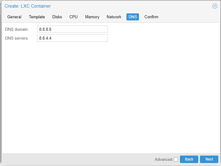
Now we are going to configure the DNS.
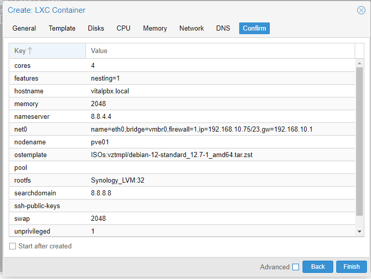
Finally, we confirm the configuration and we will proceed to create our Container.
Once our container (CT) is created, we will see it listed in our left panel, we press it with the right mouse button and start it (Start). We enter >_ Console and we will proceed to install VitalPBX.
					apt install sudo
apt update
apt upgrade -y
wget https://repo.vitalpbx.com/vitalpbx/v4.5/pbx_installer.sh
chmod +x pbx_installer.sh
./pbx_installer.sh
Now we wait about 5 minutes for the Script to finish running and we will have our VitalPBX 4.5 installed.
3.7.- Cold and hot migration
By having a three-node cluster configured, we may at some point need to migrate resources from one node to another. This can be done either cold (the machine is off) or hot (the machine is on).
First, we will perform a cold migration.
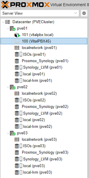
As we can see we have the machine with the ID 100 in the node pve01 and we want to migrate it to the node pve02 that does not have any virtual machine, to do this we first turn off the virtual machine and then right-click on the machine and select migration and press Migrate.

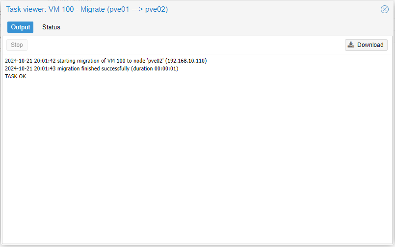
Once the migration is complete the following message will appear.
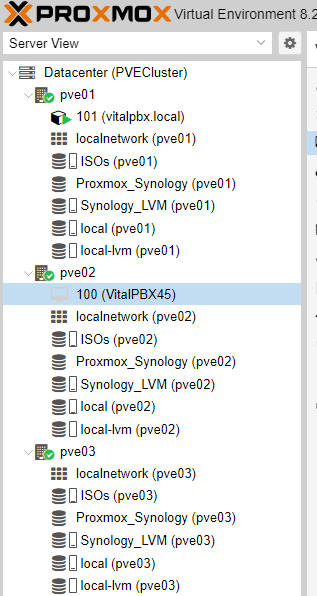
And we can see that our instance was migrated to Node 2.
Now we are going to hot migrate machine 100 that is started on node pbx01, we want to have it available on our other node without having to shut it down so we right click on the machine and select Migration.
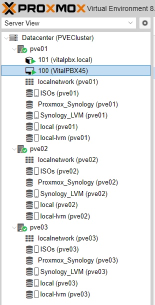
Since we have iSCSI type storage that is shared by the three nodes, the migration is transparent, meaning that there may be calls in progress and they will not stop.

Once the process is finished, it will show us the following result.
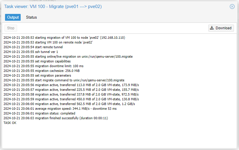
As the migration has been carried out correctly, we see that we have the machine available on our pve02 node.

Differences Between VMs and CTs in Live Migration
1. Live Migration of VMs (KVM/QEMU): Virtual machines use full virtualization (hypervisor), allowing them to run operating systems independent of the underlying hardware. During live migration, Proxmox synchronizes the memory, CPU, and state of the VM on the source node with the destination node while the VM continues to run. In the last milliseconds, Proxmox briefly pauses the VM, transfers the last bits of memory and state, and then restarts it on the destination node. This process is extremely fast, and if the network infrastructure is well configured, connectivity loss is minimal or non-existent.
Reasons for Low Connectivity Loss in VMs:
• The VM continues to operate on the source node until everything is ready on the destination node.
• The network and virtual hardware configuration remain intact, significantly reducing downtime.
• The virtualized network interfaces of the VMs can reconnect quickly without substantial changes to the network configuration.
2. Live Migration of CTs (LXC): Containers, on the other hand, are not complete virtual machines but environments that share the host kernel. Migrating a container involves moving its execution state from one node to another, and while Proxmox can perform live migration, containers tend to be more sensitive to rapid changes in the network.
During the live migration of a container, there may be a brief interruption in network connectivity because:
• The network stack of the container is temporarily halted while the container is synchronized and restored on the destination node.
• In some cases, changing the network on the destination node may take longer to apply if the nodes use different interfaces or network configurations.
• Some containers may be more sensitive to this type of interruption, especially if they depend on persistent network connections (e.g., servers requiring stable TCP sessions).
Reasons for Temporary Connectivity Loss in CTs:
1. Network Reconfiguration on the New Node: When migrating a container, the network interface inside the CT may be briefly stopped for reconfiguration on the new node. This can cause a short lapse where network connections are interrupted, which is more noticeable in containers than in VMs.
2. Synchronization of Network State: Since containers are more tightly integrated with the host operating system, migrating network interfaces may not be as smooth as in VMs, which use virtualized network interfaces managed by the hypervisor.
3. Container Dependencies on the Host Kernel: As containers use the host kernel, any minimal difference in kernel configuration or network stack between nodes can cause a slight interruption during the migration of the container.
Solutions to Minimize Connectivity Loss in Containers:
1. Network Optimization Between Nodes: Ensure that the nodes are on the same subnet and that network interfaces on the nodes are configured consistently. This will reduce the time needed for the container to restore its network connectivity.
2. Adjusting Migration Timing: Depending on your environment’s needs, you can adjust live migration parameters such as memory transfer speed or the amount of data synchronized before stopping the container. Increasing the amount of pre-synchronized memory can reduce downtime.
3. Testing Different Network Configurations: Sometimes, adjusting the type of network bridge used or utilizing VLANs can improve network connection stability during live migration.
4. Using VMs Instead of CTs for Critical Applications: If connectivity loss is a critical and ongoing issue with containers, consider using VMs for those workloads. VMs offer greater stability in live migrations compared to containers.
In summary, the temporary connectivity loss in containers is expected behavior due to the differences in how Proxmox manages the network and execution state of containers compared to virtual machines. However, with network optimization and configuration, this downtime can be minimized.
Some Reasons Why It’s Better to Use Virtual Machines (VMs) Instead of Containers in Certain Scenarios, Especially When It Comes to Environments Like VitalPBX:
1. Greater Isolation and Security:
• Virtual machines (VMs) provide a completely isolated environment, as each VM has its own operating system and dedicated resources. This significantly reduces security risks since any problem or vulnerability in one VM will not affect other VMs or the host system.
• In contrast, containers share the host system’s kernel, meaning that a problem in the kernel can compromise all containers. This level of isolation is critical when managing multiple high-value applications, such as a telecommunications system like VitalPBX.
2. Compatibility with Complex Applications:
• VMs are ideal for complex applications that require a complete operating system or have specific dependencies at the operating system level. VitalPBX is a complex application that benefits from a fully isolated virtual environment.
• Containers, on the other hand, are designed to be lightweight and efficient, but this limits their compatibility with applications that need a complete operating system environment or more complex configurations.
3. Live Migration and High Availability:
• VMs in Proxmox allow for live migration with little to no interruption. This is especially useful in a high availability (HA) environment where VMs can move between servers without stopping the service. This process is much more stable and tested in virtual machines than in containers.
• In containers, while live migration is possible, they tend to be more sensitive to network changes, which can cause brief interruptions in connectivity, affecting the experience of end users or critical services.
4. Better Resource Management:
• VMs allow for more granular and predictable resource management, as you can precisely allocate how much CPU, memory, and storage each VM should use. This is especially important when running a system like VitalPBX, which handles large volumes of calls and data.
• Containers, although lighter, rely heavily on the host operating system for resource management, which can lead to inefficiencies or conflicts if not configured correctly.
5. Better Fault Handling:
• In a high availability environment, VMs offer better recovery and fault handling mechanisms. If a server fails, Proxmox can manage the migration of VMs to another node without needing to restart applications. This is particularly beneficial for services that require high availability and constant uptime.
• In containers, while they can be migrated, they tend to be more sensitive to rapid changes in the network or host system, which can cause brief outages during the migration process.
In summary, if you are running applications like VitalPBX that require high availability, greater security, better resource management, and stability, virtual machines are the better choice compared to containers.
3.7.- High Availability Configuration
Now we will take care of configuring our cluster to work in high availability, with the intention that the resources we choose are always available.
We go to Datacenter/HA/ and in Resources we press Add.
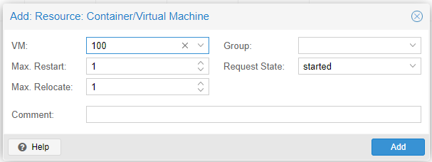
We select the instance to add in High Availability and press Add.
It is important to emphasize that it must be created in HA for each VM/CT created.
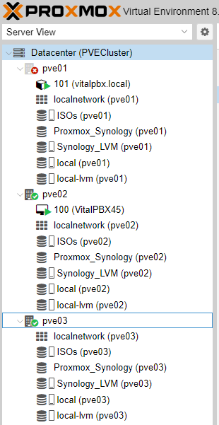
To test our high availability we shut down node 1 (pve01) and we will see how the instance stops on the next available node. To perform this test you must be connected to node2.
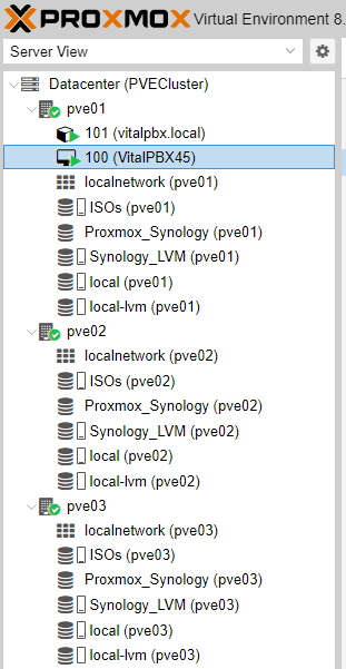
After 1 or 2 minutes we will see how our instance will appear already started on node 2 (pve02).
Note:
When shutting down Node 1 (pve01) remember that you will not have access through the interface, so we will have to access our Proxmox cluster through node 2 or 3.
The time taken to perform service migration when using the High Availability (HA) option in Proxmox can vary depending on several factors. HA functionality is designed to ensure that virtual machines (VMs) and containers (CTs) remain up and running even if a node in the cluster fails, but the failover time can be prolonged due to several technical aspects. Below I explain the possible reasons for the delay in switching from one node to another in an HA environment:
1. Node Failure Detection (Fencing)
Before Proxmox initiates the migration of VMs or CTs to another node, it must ensure that the failed node is truly unavailable. This detection process is called fencing, which ensures that a node deemed inactive does not continue running VMs or CTs in the background (this could cause “split-brain” issues, where two instances of the same machine are active simultaneously).
Reasons for Delays in Fencing:
• Failure Detection Time: The cluster must be certain that the node has failed before initiating failover. This can take a few seconds or minutes, depending on the monitoring configuration of the nodes.
• Fencing Method: Depending on how fencing is configured (e.g., using IPMI, iLO, DRAC, or other mechanisms), it may take additional time to safely power down the failed node.
Solution:
• Optimize fencing parameters, ensuring that the monitoring system can detect failures as quickly as possible without causing false positives.
• If possible, use faster fencing mechanisms.
2. Restarting or Restoring VMs/CTs on the Destination Node
Once the failed node has been “fenced” and Proxmox has decided that the VM or CT needs to be migrated, the next step is to start the instance on the new node. In HA environments, this involves booting the VMs or CTs from scratch since the failed node could not complete a live migration.
Reasons for Delays:
• VM/CT Boot Time: Depending on the amount of memory and resources required by a VM or CT, booting on the new node may take longer.
• Data Synchronization: If storage is not fully shared or there is any delay in the storage network, it may take longer to restore the state of the VMs or CTs on the new node.
• Network Dependencies: When restarting a VM or CT, network configurations must be reapplied on the destination node. If the network on the destination node takes time to respond or apply the correct configurations, this could cause delays in restoration.
Solution:
• Ensure that shared storage and networking between nodes are optimized to minimize data synchronization times.
• Use fast local disks and properly configure shared storage to minimize boot time.
3. HA Timeout Configuration
Proxmox HA has a timeout parameter that defines how long the system waits before taking failover action. By default, there may be a delay to avoid triggering failover due to temporary errors or false positives.
Solution:
• Review and adjust timeout and retry values in the HA configuration to better suit your availability and speed needs. You can reduce detection and response times, but be careful not to set it too low to avoid premature failures.
• The values in the crm config (the HA management system) can be adjusted, such as by decreasing wait times or increasing monitoring frequency between nodes.
4. Resource Capacity on the Destination Node
If the destination node does not have sufficient resources (CPU, RAM, storage) available to run the VM or CT that needs to migrate, the process may be slower or even fail.
Solution:
• Ensure that the nodes in your cluster are balanced in terms of resource capacity. Implement a resource monitoring system to avoid overloading any particular node.
• Proxmox can distribute VMs and CTs more effectively if all nodes have sufficient resource margins to absorb new loads during an HA situation.
5. Shared Networks and Storage
If the interconnection networks between the nodes of the cluster or the shared storage system are not adequately configured or are slow, it can have a direct impact on failover speed.
Factors That May Affect:
• Network Speed: If the cluster network is not fast enough or has latency issues, failover time may increase.
• Storage: If the shared storage between nodes is not optimized (e.g., high latencies in an iSCSI or NFS storage), the migration process will be slower.
Solution:
• Improve the speed and reliability of the network between nodes, ideally using dedicated high-speed networks (e.g., 10GbE or more).
• Optimize shared storage to ensure fast response times when accessing disks during VM or CT migration.
6. Cluster Overload
If the Proxmox cluster is under heavy load (e.g., CPU and memory maxed out on several nodes), failover may take longer because the resources of the destination node are already occupied managing other tasks.
Solution:
• Monitor the cluster workload and ensure that nodes have sufficient capacity available to manage failovers quickly.
• Implement load balancing policies to better distribute VMs and CTs across nodes.
7. Floating IP or Load Balancing Configuration
In environments where network services are critical, you may need to configure floating IPs or load balancing solutions to automatically redirect network traffic to the new node after a failover. This can cause additional delays if not configured correctly.
Summary of Solutions to Improve Failover Time in HA:
1. Optimize fencing and failover configuration for faster detection times.
2. Adjust HA parameters such as timeout to reduce the wait time before executing failover.
3. Optimize shared network and storage to ensure that data and connectivity synchronize quickly.
4. Review resource capacity on destination nodes and avoid overloading nodes.
5. Improve cluster network speed and use dedicated networks if possible.
By following these steps, you can reduce the time it takes for failover in Proxmox HA and improve the overall availability of your services.
3.8.- Installing and configuring SBC based on Kamailio
In our VoIP environment with VitalPBX, the use of a dSIPRouter-based SBC with Kamailio is key to improving system security and efficiency. In this case, we did not deploy it for load balancing, but as a SIP Proxy that protects our network against external attacks, such as DDoS and fraud, and facilitates NAT management for SIP connections.
By centralizing and controlling SIP registration and authentication requests, the SBC adds a critical layer of protection, improves interoperability with third-party vendors, and ensures greater stability and resilience without compromising system performance.
Installing and configuring dSIPRouter:
The first thing to do is to install it on a Debian 12 VM, with about 6 CPU cores and 6GB of RAM.
Although it is not strictly necessary, we recommend having a valid domain on the server where we will install dSIPRouuter. In our case we will do it without a valid domain, so the dSIPRouter installer will generate a Self-Signed certificate.
					apt-get update -y
apt-get install -y git
cd /opt
git clone https://github.com/dOpensource/dsiprouter.git
cd dsiprouter
./dsiprouter.sh install -all
At the end of the installation, the following screen will be displayed, where we can see the URL, User and Password to use to enter the dSIPRouter administration via WEB.
					------------------------------------
RTPEngine Installation is complete!
------------------------------------


     _  _____ _____ _____  _____             _
    | |/ ____|_   _|  __ \|  __ \           | |
  __| | (___   | | | |__) | |__) |___  _   _| |_ ___ _ __
 / _` |\___ \  | | |  ___/|  _  // _ \| | | | __/ _ \ '__|
| (_| |____) |_| |_| |    | | \ \ (_) | |_| | ||  __/ |
 \__,_|_____/|_____|_|    |_|  \_\___/ \__,_|\__\___|_|

Built in Detroit, USA - Powered by Kamailio

Support can be purchased from https://dsiprouter.org/

Thanks to our sponsor: dOpenSource (https://dopensource.com)


Your systems credentials are below (keep in a safe place)
dSIPRouter GUI Username: admin
dSIPRouter GUI Password: Z8KuoZUm9Rm5X6lnQDJYAopre64awP80mf8tnVQCN8BhXSBn5GApnGPEsIfAiHX8
dSIPRouter API Token: 7jiNdkr9ufgwFaQE0e12cKcWd6FHqqAWaFYMKpV0hor1ntB3rZaSjJ9HclhA5KxL
dSIPRouter IPC Password: r6ThM9Ja5CcP9FO9Z66v2vR14FAJER7sV9DPDPd2xX87JMv8ncWGXe15ncuc0ET0
Kamailio DB Username: kamailio
Kamailio DB Password: n7QOW7EHZiE1pviEifVjdsDSnvpGFbTzWK2Ba6XpcwKFefg6hiuHy35YyaumJCoe

You can access the dSIPRouter WEB GUI here
Domain Name: https://dsiprouter:5000
External IP: https://186.77.197.102:5000
Internal IP: https://192.168.10.101:5000

You can access the dSIPRouter REST API here
External IP: https://186.77.197.102:5000
Internal IP: https://192.168.10.101:5000

You can access the dSIPRouter IPC API here
UNIX Domain Socket: /run/dsiprouter/ipc.sock

You can access the Kamailio DB here
Database Host: localhost:3306
Database Name: kamailio
Sometimes it is necessary to enable the mariadb service, since we run the risk that when restarting the server it will not start.
systemctl enable mariadb
Once installed, you can access the dSIPRouter administration interface. Access the web interface via the following URL in your browser:
Once dSIPRouter is installed on Node 1, we will proceed to make the necessary configurations to use it as a SIP proxy.
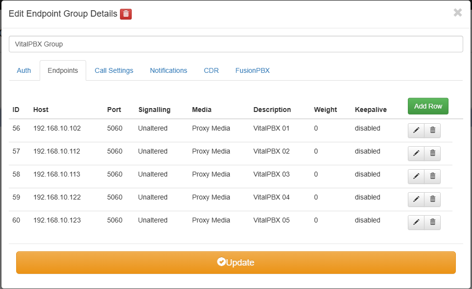
First, we will define a scenario with 5 instances of VitalPBX, 1 located on Node 1, 2 on Node 2 and 2 on Node 3.
Nodo 1:
VitalPBX
IP: 192.168.10.102
dSIPRouter
IP: 192.168.10.103
Nodo 2:
VitalPBX
IP: 192.168.10.112
VitalPBX
IP: 192.168.10.113
Nodo 3:
VitalPBX
IP: 192.168.10.122
VitalPBX
IP: 192.168.10.123
Create Endpoint Group
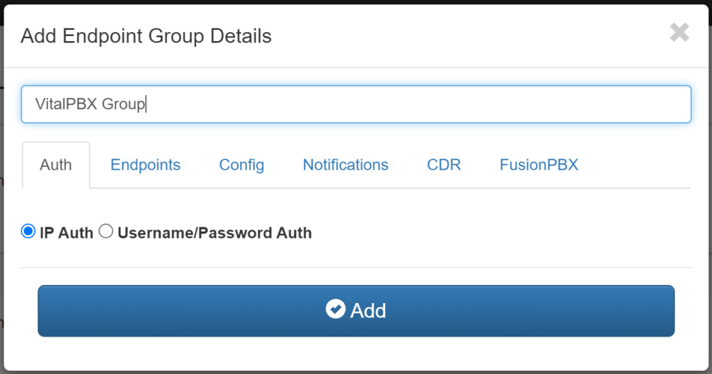
We proceed to create the Endpoints, once created we will have the following result.
Now we will proceed to create a domain for each Endpoint (VitalPBX).

After creating the 5 domains, we should see these:

Remember that after configuring it is necessary to do a Kamailio Reload.
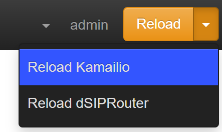
Proxy Configuration in VitalPBX
Now we go to VitalPBX SETTINGS/Technology Settings/Device Profile and select “Default PJSIP Profile”
Outbound Proxy: sip:192.168.10.103;\lr
We save and apply changes.
It is also recommended to add the dSIPRouter IP to the White List in the VitalPBX Firewall.
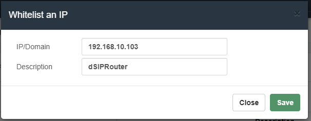
Device Configuration
In order to access VitalPBX now, four parameters must be taken into account:
• SIP Server, is the domain that we define associated with the Endpoints, e.g.: vpbx01.vitalpbx.xyz
• Proxy Server, is the IP or domain of our SIP Proxy (dSIPRouter).
• User, user defined when creating the extension in VitalPBX, usually it is the extension number.
• Password, key associated with the user.
For which we are going to create the Extension 2000 in /PBX/Extensions.
On a Yealink T58 IP phone, this would be the configuration:
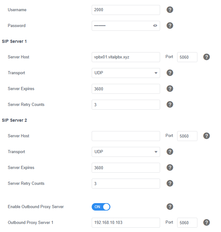
Where:
Server Host, is the domain created in dSIPRouter that points to VitalPBX 01.
Outbound Proxy Server 1, is the domain or IP of our dSIPRouter server.
User, is the user of the extension created in VitalPBX.
Password, is the password for the extension created in VitalPBX.
4.- Load Tests
1. Test Summary:
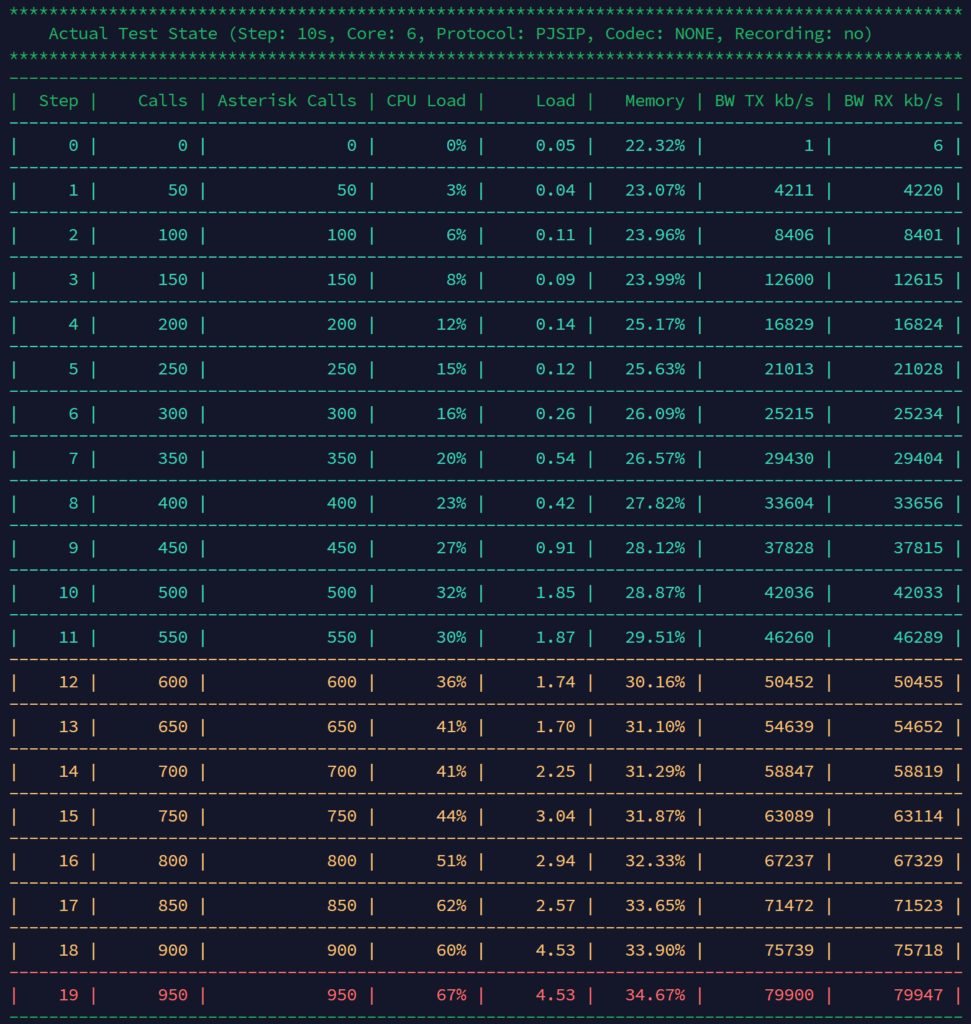
• The test was performed with a 10 second interval between each step, using the PJSIP protocol and without recording.
• The load is increased in steps of 50 calls, starting with 0 calls and reaching a maximum of 950 concurrent calls.
• The configuration includes 6 CPU cores and bandwidth usage (BW) in kb/s is measured both in transmission (TX) and reception (RX).
2. Use of Resources:
• CPU: CPU load starts at 3% at 50 concurrent calls and gradually increases. Starting at 850 calls, CPU reaches 62%, rising to 67% at the maximum of 950 calls.
• System Load: It stays relatively low until around 450 calls, but starts to rise more rapidly after that point. The system stabilizes at a load level of about 4.53 in the last two steps, with 900 and 950 calls.
• Memory: Memory usage starts at 22.32% and slowly increases as load increases, reaching 34.67% at the maximum concurrent calls.
3. Bandwidth:
• TX and RX BW (kb/s): The transmission and reception bandwidth increases proportionally to the number of calls. For 50 calls, it is around 4,200 kb/s, and at the maximum of 950 calls it reaches approximately 79,900 kb/s in both directions.
4. Critical Points:
• Starting at 500 calls, a significant increase in system load and CPU usage is observed, although the system still handles the load up to 950 calls.
• The last test, with 950 concurrent calls, shows the CPU at 67% and system load at 4.53, indicating that it is approaching the capacity limit, as a CPU load of 67% and a system load around 4 on a 6-core system is approaching saturation.
• Bandwidth also reaches high levels, which could be a limiting factor on capacity-restricted networks.
5. External Factors to Consider:
• Other Applications on the Same Server: If the server is running additional applications in addition to Asterisk, the CPU and memory load may be affected, which would decrease the capacity of concurrent calls that the system can handle stably.
• Call Recording: The test did not include call recording. Enabling recording can significantly increase CPU, memory, and disk space usage. If recording is planned, it is recommended to adjust the maximum call capacity to avoid overload.
• Compression Codecs: Using compression codecs (such as G.729 or Opus) instead of uncompressed codecs will increase the processing load on the CPU. This is particularly relevant if used in a high traffic environment, such as a call center.
• Call Center Environment and High Traffic: In a call center scenario, call traffic is high and constant, which can put additional pressure on the Asterisk system. Additionally, if network traffic is high, bandwidth could become a limiting factor. It is recommended to monitor the network and server in real time to adjust capacity as needed.
• WebRTC Client (VitXi): Using a WebRTC client such as VitXi also impacts the system, as WebRTC involves additional processing load to handle real-time encryption and decryption (SRTP). This can increase CPU and bandwidth usage, particularly in high call concurrency scenarios such as a call center.
6. Conclusion:
• This system is capable of handling up to approximately 900 concurrent calls effectively before approaching a high load state that could impact performance.
• To maintain a safety margin and avoid saturation, a recommended limit could be set around 550 concurrent calls.
• This analysis suggests that with 6 CPU cores, the Asterisk system performs well up to a certain load limit before potential stability or performance issues begin to occur.
5.- Conclusions
Installing a 3-server Proxmox cluster offers a robust and scalable infrastructure to handle a VoIP environment with high availability and extension load requirements. This configuration leverages Proxmox’s High Availability (HA) capabilities to minimize downtime and ensure service continuity.
Configuration Details:
1. Primary Proxmox Server:
• Two virtual machines (VMs) were created:
o dSIPRouter: 6 cores and 8 GB RAM, configured as a SIP proxy that manages SIP traffic, providing a single entry point for calls and improving security and efficiency in traffic distribution.
o VitalPBX: 6 cores and 8 GB RAM, installed to manage communications and extension handling on this server.
2. Secondary Proxmox Servers:
• Two additional VitalPBX VMs with 6 cores and 8 GB of RAM each were installed on each of the other two Proxmox nodes, thus distributing the load and providing redundancy.
3. Advantages of High Availability Configuration:
• Automatic Failover and Redundancy: In the event of a failure on any of the Proxmox nodes, the cluster can automatically or manually migrate the VMs to another active node, ensuring that both dSIPRouter and the VitalPBX servers continue to operate without interruption.
• Load Distribution: The distributed configuration of VitalPBX across three nodes allows calls and extensions to be managed efficiently, avoiding overloading a single server and ensuring optimal performance.
• Scalability: This architecture allows the number of supported extensions to be scaled up to between 10,000 and 15,000, as the processing load is distributed, and the infrastructure can be expanded if greater capacity is needed.
Extension Management Capacity:
Thanks to the dedicated hardware configuration (6 cores and 8 GB of RAM in each VitalPBX VM), this infrastructure can comfortably handle a range of between 10,000 and 15,000 extensions. This capacity is achieved thanks to:
• Resource Optimization through dSIPRouter: The use of dSIPRouter as a SIP proxy optimizes the traffic flow to the VitalPBX servers, alleviating the direct load on them and allowing greater efficiency in the management of extensions.
• Distributed VitalPBX Configuration: With several instances of VitalPBX operating in parallel, the management of calls and extensions is distributed, facilitating the administration of large volumes of users and maintaining stable performance.
Deploying this Proxmox cluster with dSIPRouter and VitalPBX provides a highly available and scalable infrastructure, ideal for businesses requiring a reliable VoIP solution capable of managing large numbers of extensions. Proxmox’s high availability capability ensures service continuity in the event of failures, and the distributed configuration allows it to handle a considerable extension load, maximizing system performance and efficiency. This solution is suitable for demanding environments such as call centers or businesses with intensive telecommunications needs.


